This week we're learning about Output Devices, measuring power consumption using a power supply, making stuff move, write using our own microcontroller pcb while hustling to celeberate Eid.
Requirements
- Measure the power consumption of an output device.
- Document your work to the group work page and reflect on your individual page what you learned
Group Assignment
Individual Assignment
- Add an output device to a microcontroller board you've designed and program it to do something.
Softwares 💻
- KiCAD
- MODS
- GIMP
- Arduino IDE
Group Assignment
What kills you the Volt or the ampere? the current or the voltags? I never wanted to find out to be honest so I dodged the power supply like it was the plague. But time has come to face the tool I feared and really understand why the servos need external power source and see the ohm's law in motion.
In the group assignment our instructors Amany and Saeed told us how to use a DC power supply to supply a lamp a certain voltage and see the corresponding current on the power supply's screen.
As shown in the image below, we connected the crocodile clips to the lamp and the power supply. We set the voltage to 12 Volts & the current to 0.61 Ampere. We then deduced the power using ohm's law "p=IV" which was 7.32 Watt. We amplified the voltage and saw the light begin to become brighter. This is considered alright since the Lamp can handle up to 10 Watt.
After that we wanted to measure the real voltage and current running through the lamp. To measure the current, we connected the multimeter in series finally I get the right name for the right connection always mix those up in English but not in Arabic! with the lamp and changed the probe to the current side and measured again. Also twe discovered their's a 0.02 ampere increase this because of the resistance is the crocodiles
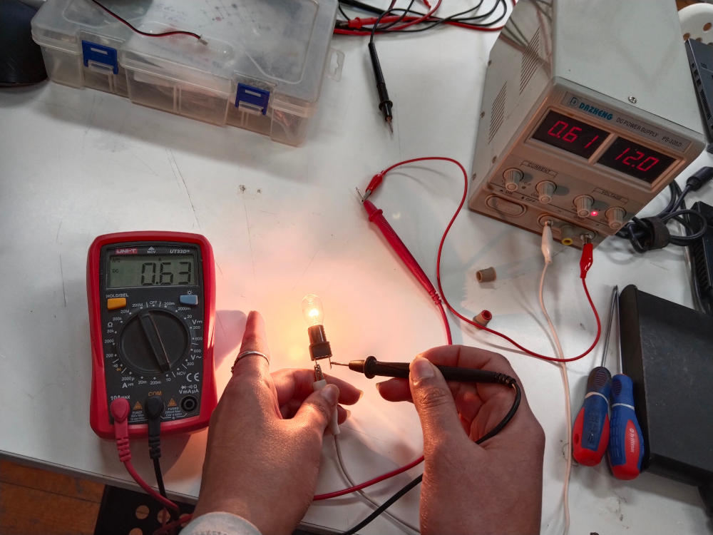
Measuring current
We notices the current reading was 0.02 higher than was put on the screen so the crocodiles have resistance we didn't account for.
Individual Assignment
Moving motors, making kindles
Moving Motors
My final project is all about movement and from the deepest bottom of my heart I like seeing things move. Also, Saeed introduced us a new component that can be handy in our toolkit: The mosfet. Here's a very thorough video by The Engineering Mindset youtube channel. The mosfets are spmething like a switch think the relay but without the mechanical aspect. It instead voltage-controlled, meaning by applying a certain voltage to the pin called gate, it will allow the current to flow.
The MOSFET is Classified into two types based on the type of operations, namely Enhancement mode MOSFET and Depletion mode MOSFET, it's further classified based on the material used for construction as n-channel and p-channel. The difference between n-channel and p-channel is that in an N-channel, switch will remain open until a gate voltage is provided. When the gate pin receives the voltage, the switch (between Drain and Source) will get closed.
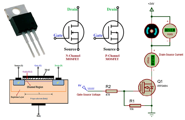
Credits: Components101
PCB Design
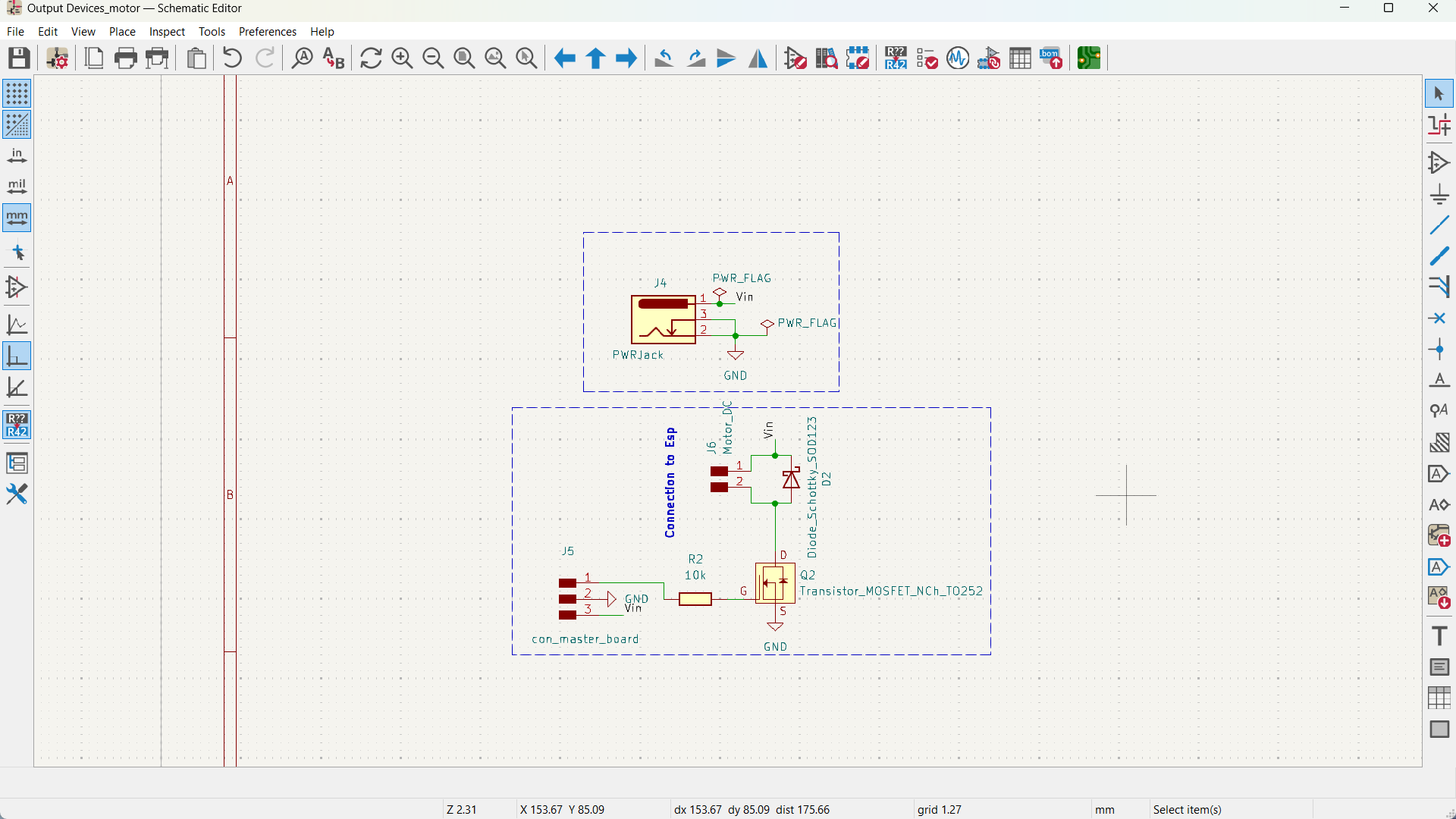
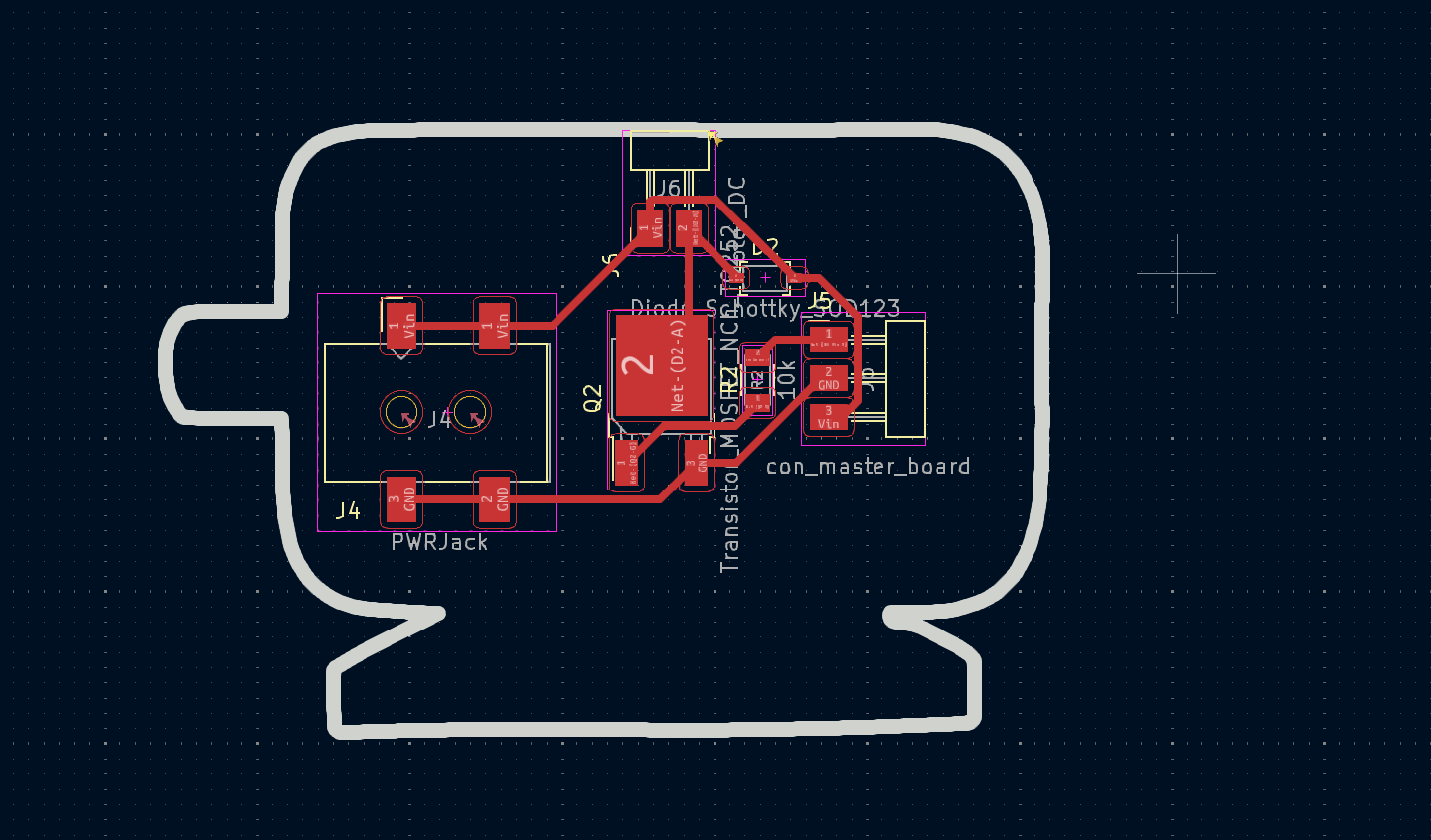
I'll create another board with the mosfet on it and connect it with the microcontroller board I made in Week6 here and to control a dc motor and I'll be using an n-channel mosfet since I want my motor to not work until a signal/voltage is provided.
My Components
| Component | Quantity | Function |
|---|---|---|
| DC jack | 1 | power jack for the adaptor |
| Resistor | 1 | 10k pull-down resistor |
| Diode | 1 | Flyback Diode to not damage the circuit because of the Motor's large inductance. |
| PinHeaders | 2 | Signal, vin, and GND for main board + Motor pins |
before I ran to make the board in kicad, Saeed made us do the circuit on a breadboard.
The Code
         int motor = 33;

       void setup() {
      pinMode(motor, OUTPUT);
        }

     void loop() {
       digitalWrite(motor, HIGH);
       delay(1000);
      digitalWrite(motor, LOW);
       delay(1000);
        }
Schematic & Layout
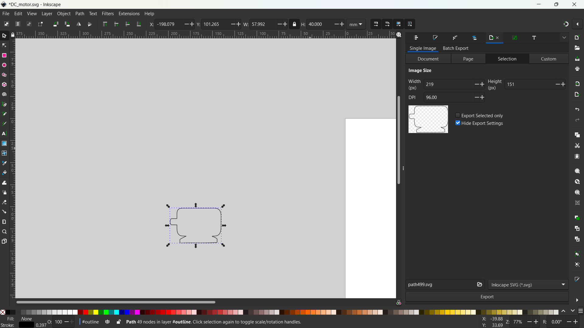
After that I jumped to Kicad and tried to replicate as always trying my best to make it neat and added a outline that looks like a motor to avoid the mundane rectangle .
Fabrication & Testing
I used the same workflow introduced in week 6 as well began fabricating my board.
After Soldering
I supplied the motor with 5v Adaptor and made sure I disconnected the FTDI because I didn't want to lose my laptop hehe..
Then I used the same code mentioned above put changed the pin number to my PWM pinheader IO17 and Voila!
Challenges
First working while fasting in Ramadan is exhausting but I managed. Second, I had a lot of challenges with drawing the schematic of the motor pcb and I ended up making a mistake. I put a pull up resistor instead of a pull-down.. I made sure in the code to make the motor low before disconnecting the power.
Moving Servo
I also wanted to move the servo motor becuase I used it in Embedded programming week and I want to use it in future weeks and recreate the movement I wanted to make towards a planet via NASA API. I'll be controlling it with my board I made in Input Devices week since I added power pins to it. I'll run a sweep code and see how it goes!
The Code
#include ESP32Servo.h>
 Servo myservo;
int pos = 0;
int servoPin = 27;
 void setup() {
    ESP32PWM::allocateTimer(0);
   ESP32PWM::allocateTimer(1);
   ESP32PWM::allocateTimer(2);
   ESP32PWM::allocateTimer(3);
  myservo.setPeriodHertz(50);    // standard 50 hz servo
   myservo.attach(servoPin, 1000, 2000);
  }

 void loop() {

  for (pos = 0; pos <= 180; pos += 1) { // goes from 0 degrees to 180 degrees in 1 deg steps
  myservo.write(pos);    // goes to position stored in pos variable
   delay(15);             // waits 15ms to reach position
    }
  for (pos = 180; pos >= 0; pos -= 1) {
   myservo.write(pos);    // goes to position stored in pos variable
    delay(15);
  }
   }
Output
Voila!
Making Kindles
The first thing i gifted my self in 2023 after offered a full-time job as a fabrication Specialist was a kindle. I loved it so much and I carry it with me wherever I go. It was a great joy to to test an E-paper lcd for this week.
Currently reading "Slow Productivity" on my kindle.
Well I found an overly simple documentation for the WeAct Studion E-paper 2.13' module I have here. But it's hardly a documentaion and only has one example for each board with no wiring diagram. It's based though on this library by an E-paper guru called ZinggGM.
| Pin | Jumper Colour | name on PCB | IO |
|---|---|---|---|
| SCL | Green | MOSI | 23 |
| SDA | Blue | CLK | 18 |
| D/C | Black | TX2 | 17 |
| CS | Purple | CS | 5 |
| BUSY | Brown | Touch + ADA_pin | 4 |
| RST | Red | RX2 | 16 |
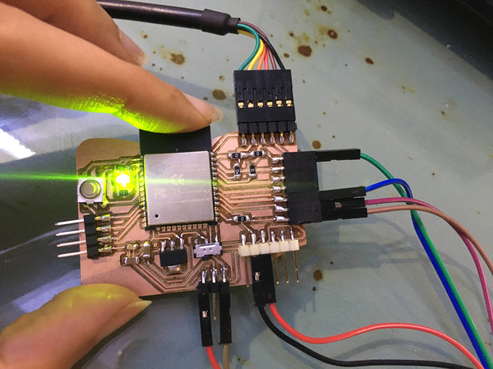
Challenges
The first struggle: To I2C or not to I2C
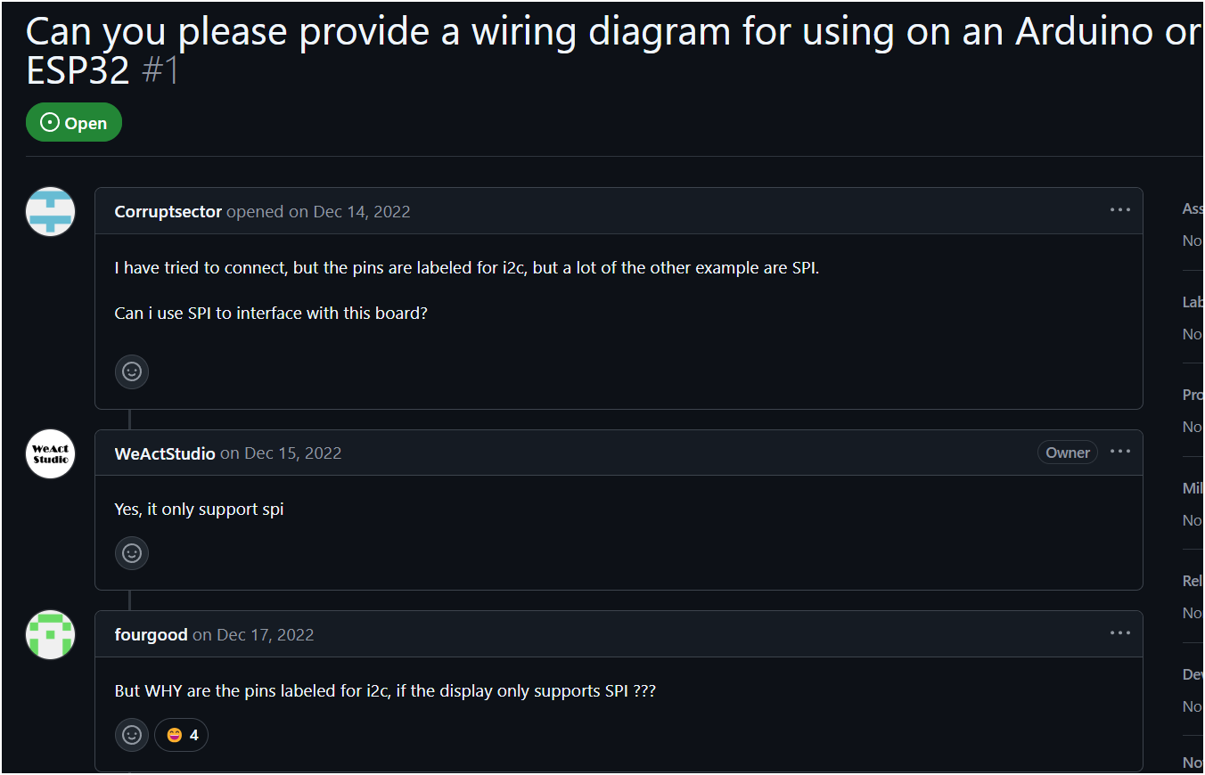
Short answer is to not to I2C but to SPI because some lunatic decided that people would understand that the SCL and SDA written on the E-paper's pins is ACTUALLY MISO AND CLK. I don't know who you're but I'll look out for you, I'll find you and hunt in your dreams.
The second struggle: boi oh boi what is that documentation.
The example provided in the WEAct Studio on Github is an example taken from a very-well-documented-extremely-overwhelming-library. It assumebly suppots most of E-paper LCDs except the one I got.
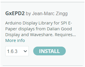
after laughing for half an hour on my mistake on the SPI connection and correcting the wiring the lcd didn't even say hello. So I ran through the issues on Github.
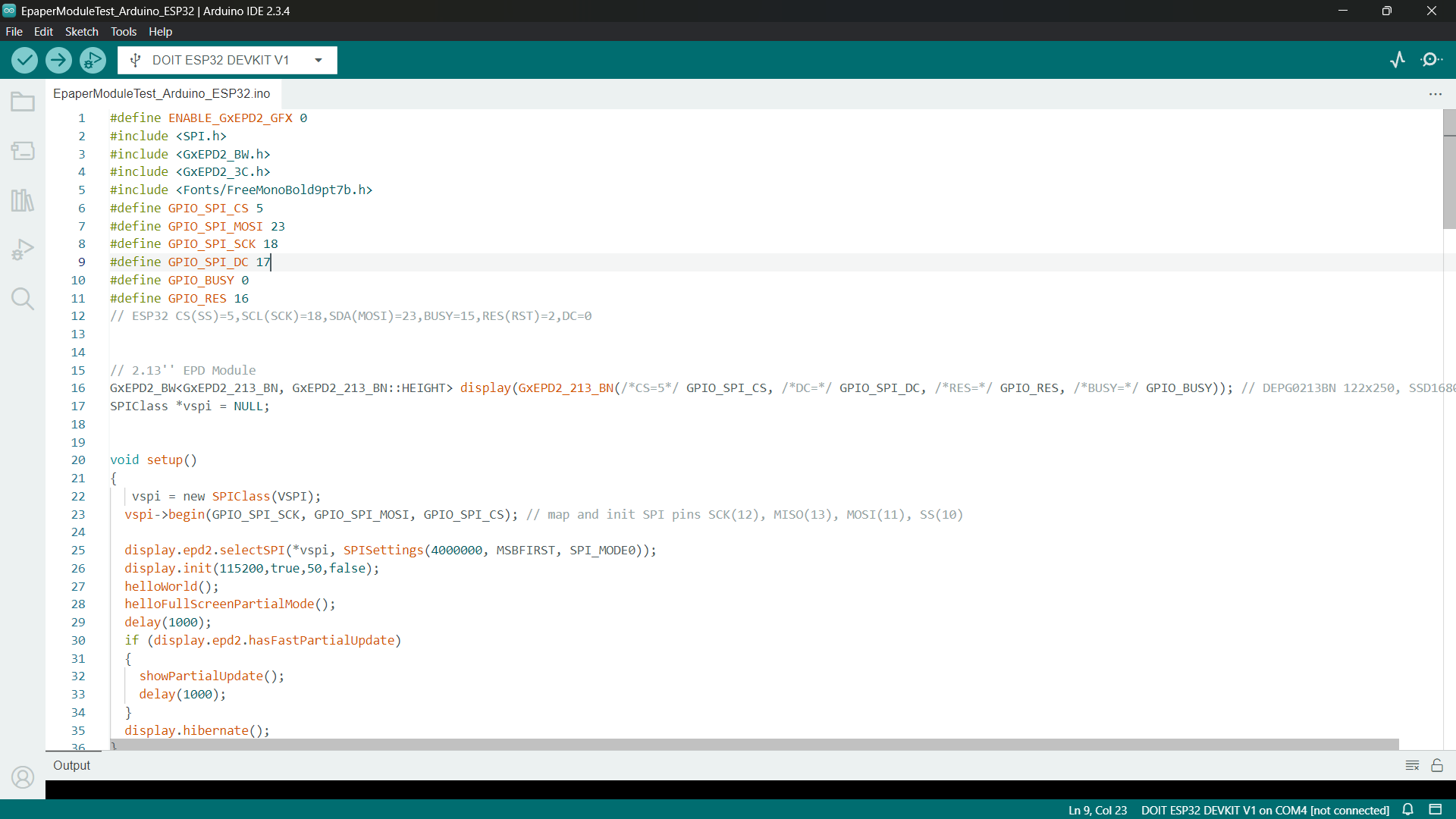
My issue was that I didn't want to use the preconfigured pins from the example but choose my own so I found this method I tried this method but it still didn't work. I'll try it again.
This didn't discourage me on the contrary I'm actually grateful I found out-and applied to participate in- a project called The Open Book . It' an open hardware e-book reader designed around the ESP32-S3. The Open Book stakes out an alternate vision for developing personal computing devices, using the humble e-book reader as its ideological canvas.
Making Kindles Round 2!
To debug the problem I seekded Tarek 's help and we tried uploading the code on an ESP-Wroom-32 using the same configured pins in the WeAct Github and It worked fine!
Well! Well! It worked fine then let's test it on my own pcb and make it greet me not the world and see. I
changed the assignmed pin number of BUSY, DC, RES.
display(GxEPD2_213_BN(/*CS=5*/ 5, /*DC=*/ 0, /*RES=*/ 2, /*BUSY=*/ 15)); assigned pins in the
library.
display(GxEPD2_213_BN(/*CS=5*/ 5, /*DC=*/ 21, /*RES=*/ 4, /*BUSY=*/ 22)); my pins.
It Worked!
I used the same code from the example and changed the const char inside the HelloweAct array to to be my name.
Time for a literature test!
The Code
#define ENABLE_GxEPD2_GFX 0
#include GxEPD2_3C.h>
#include Fonts/FreeMonoBold9pt7b.h>

    // 2.13'' EPD Module
  GxEPD2_BW GxEPD2_213_BN, GxEPD2_213_BN::HEIGHT> display(GxEPD2_213_BN(/*CS=5*/ 5, /*DC=*/ 21, /*RES=*/ 4, /*BUSY=*/ 22)); // DEPG0213BN 122x250, SSD1680

 void setup()
   {
  display.init(115200,true,50,false);
   helloWorld();
    helloFullScreenPartialMode();
     delay(1000);
   if (display.epd2.hasFastPartialUpdate)
  {
     showPartialUpdate();
   delay(1000);
   }
    display.hibernate();
    }

   const char HelloWorld[] = "Hello!";
     const char HelloWeACtStudio[] = "The Big Brother is Watching You";

     void helloWorld()
         {
   display.setRotation(1);
     display.setFont(&FreeMonoBold9pt7b);
      display.setTextColor(GxEPD_BLACK);
      int16_t tbx, tby; uint16_t tbw, tbh;
     display.getTextBounds(HelloWorld, 0, 0, &tbx, &tby, &tbw, &tbh);
       uint16_t x = ((display.width() - tbw) / 2) - tbx;
       uint16_t y = ((display.height() - tbh) / 2) - tby;
     display.setFullWindow();
 display.firstPage();
    do
   {
      display.fillScreen(GxEPD_WHITE);
      display.setCursor(x, y-tbh);
   display.print(HelloWorld);
     display.setTextColor(display.epd2.hasColor ? GxEPD_RED : GxEPD_BLACK);
    display.getTextBounds(HelloWeACtStudio, 0, 0, &tbx, &tby, &tbw, &tbh);
     x = ((display.width() - tbw) / 2) - tbx;
  display.setCursor(x, y+tbh);
        display.print(HelloWeACtStudio);
         }
       while (display.nextPage());
              }

      void helloFullScreenPartialMode()
        {
    const char fullscreen[] = "full screen update";
     const char fpm[] = "fast partial mode";
     const char spm[] = "slow partial mode";
       const char npm[] = "no partial mode";
   display.setPartialWindow(0, 0, display.width(), display.height());
       display.setRotation(1);
   display.setFont(&FreeMonoBold9pt7b);
      if (display.epd2.WIDTH < 104) display.setFont(0);
      display.setTextColor(GxEPD_BLACK);
     const char* updatemode;
      if (display.epd2.hasFastPartialUpdate)
      {
        updatemode = fpm;
       }
         else if (display.epd2.hasPartialUpdate)
          {
        updatemode = spm;
       }
         else
{
updatemode = npm;
}
int16_t tbx, tby; uint16_t tbw, tbh;
// center update text
display.getTextBounds(fullscreen, 0, 0, &tbx, &tby, &tbw, &tbh);
uint16_t utx = ((display.width() - tbw) / 2) - tbx;
uint16_t uty = ((display.height() / 4) - tbh / 2) - tby;

display.getTextBounds(updatemode, 0, 0, &tbx, &tby, &tbw, &tbh);
uint16_t umx = ((display.width() - tbw) / 2) - tbx;
uint16_t umy = ((display.height() * 3 / 4) - tbh / 2) - tby;

display.getTextBounds(HelloWorld, 0, 0, &tbx, &tby, &tbw, &tbh);
uint16_t hwx = ((display.width() - tbw) / 2) - tbx;
uint16_t hwy = ((display.height() - tbh) / 2) - tby;
display.firstPage();
do
              {
display.fillScreen(GxEPD_WHITE);
display.setCursor(hwx, hwy);
display.print(HelloWorld);
display.setCursor(utx, uty);
display.print(fullscreen);
display.setCursor(umx, umy);
display.print(updatemode);
}
while (display.nextPage());
}
void showPartialUpdate()
{
// some useful background
helloWorld();
// use asymmetric values for test
uint16_t box_x = 10;
uint16_t box_y = 15;
uint16_t box_w = 70;
uint16_t box_h = 20;
uint16_t cursor_y = box_y + box_h - 6;
if (display.epd2.WIDTH < 104) cursor_y = box_y + 6;
float value = 13.95;
uint16_t incr = display.epd2.hasFastPartialUpdate ? 1 : 3;
display.setFont(&FreeMonoBold9pt7b);
if (display.epd2.WIDTH < 104) display.setFont(0);
display.setTextColor(GxEPD_BLACK);
// show where the update box is
for (uint16_t r = 0; r < 4; r++)
{
display.setRotation(r);
display.setPartialWindow(box_x, box_y, box_w, box_h);
display.firstPage();
do
{
display.fillRect(box_x, box_y, box_w, box_h, GxEPD_BLACK);
//display.fillScreen(GxEPD_BLACK);
}
while (display.nextPage());
delay(2000);
display.firstPage();
do
{
display.fillRect(box_x, box_y, box_w, box_h, GxEPD_WHITE);
}
while (display.nextPage());
delay(1000);
}
//return;
// show updates in the update box
for (uint16_t r = 0; r < 4; r++)
{
display.setRotation(r);
display.setPartialWindow(box_x, box_y, box_w, box_h);
for (uint16_t i = 1; i <= 10; i += incr)
                  {
display.firstPage();
do
{
display.fillRect(box_x, box_y, box_w, box_h, GxEPD_WHITE);
display.setCursor(box_x, cursor_y);
display.print(value * i, 2);
}
while (display.nextPage());
delay(500);
}
delay(1000);
display.firstPage();
do
{
display.fillRect(box_x, box_y, box_w, box_h, GxEPD_WHITE);
}
while (display.nextPage());
delay(1000);
}
}

void loop() {
// put your main code here, to run repeatedly:
}